
Technology Note 214
KinExA Pressure Data
The Pressure Transducer is a feature that is incorporated in the KinExA® 3200 model. Throughout an experiment, the transducer measures fluid pressure and then converts that pressure into electrical signals that can be graphed and monitored in real time. The addition of the transducer is useful when isolating and fixing flow related problems. Below are brief descriptions of the different sections of the pressure traces and how to exploit them to identify potential problems.
A Standard Pressure Trace for the KinExA 3200
The pressure trace seen in Figure 1 was generated using the standard flow rates and volumes shown in the standard Kd template timing file. Below the pressure trace are marked locations indicating when the instrument is performing a specific function: backflush, expel to waste, pull from buffer, inject, particle reservoir, or sample lines. Understanding what is happening in each segment can help KinExA users and Sapidyne representatives understand where a problem may be occurring. The following outlines how the pressure data may be used to diagnose and correct KinExA related problems.

Figure 1. This pressure trace is for 13 samples run in duplicate. Each one of the pressure traces are reproducible and overlay nicely.
Bead Handling
The bead handling portion of an experiment is what happens before time=0 in preparation for sample handling which begins at time=0. The first procedure of bead handling is a backflush, which expels beads from the flow cell. Examining backflush pressure is useful when identifying potential problems. The backflush pressure should stay between 5 V and 9 V of positive pressure. If an Autosampler is in use, the pressure should stay between 10 V and 14 V of positive pressure. In either case, the pressure should be relatively constant during each backflush period.
Figure 2A shows a significant decrease during the backflush. Although difficult to see, each cycle decreases in positive pressure and the slant is reproducible. If this occurs, try manually flushing the Backflush Isolation Valve with dH2O. This can be accomplished by using a syringe with a female lure to 1/4-28 adapter from the flushing kit (Part #344345). Please follow this procedure to flush the backflush isolation valve:
- Disconnect the tubing nuts on the backflush isolation valve and screw the adapter into the left side of the valve.
- Remove the tubing from the backflush peristaltic pump so buffer does not flow out of the backflush line.
- Select Backflush from the KinExA Pro software to open the valve. While it is open, push dH2O into the valve.
- Make sure to have a paper towel or a beaker to capture water as it exits the right side of the valve.
- You may need to flush the valve several times in both directions until liquid moves easily in and out of the valve while the pump is running.
- After flushing, place peristaltic pump tubing in the correct place and make sure the tubing nuts are tight.
If the pressure on the backflush increases over the course of an experiment (Figure 2B), or the pressure exceeds 9V on the instrument or 14V on the Autosampler, then replace the flow cell. See HG203 Flow Cell Replacement & Alignment for instructions on replacing the flow cell.
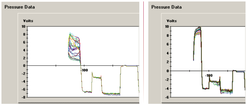
Figure 2A. Each cycle decreases in backflush pressure. Figure 2B. Each cycle increases in backflush pressure.
Sample Handling
Negative pressure for samples will be more or less negative depending on flow rate. If the flow rate is held constant throughout the experiment, then the pressure traces should overlay for multiple samples.
The pressure transducer has a finite life, and therefore is replaced during a preventive maintenance visit.
Erratic pressure sample handling traces are usually due to bubbles which may be introduced into the system in a variety of different ways. When bubbles are observed, check for the following:
- Buffer bottle, sample and label tubes, and the particle reservoir bottle have fluid.
- Buffer line and sample lines are at the bottom of the bottle or tubes.
- Timing File for the Autosampler went to the correct position.
- Tubing nuts are properly tightened and ferrules are correctly installed (especially after a flow cell change).
- A leak in the system (e.g. isolation valves, 4-way connector, sample selection valve, etc.).
For help identifying flow related problems, please contact a Sapidyne Representative.
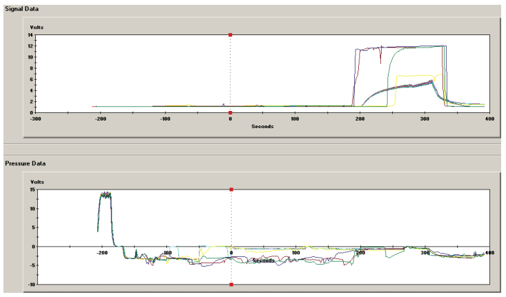
Figure 3. Particle reservoir ran dry introducing bubbles.