
How to Guide 214

Flow Cell Selection and Information

How to Guide 214 • HG214R1
8 Nov 2012 • © 2012 Sapidyne Instruments Inc.

The KinExA® flow cell is a capillary tube with a 20 Micron screen for retaining the solid phase. The lifespan of a flow cell varies widely due to factors such as: the type of beads that are being used, what materials are run through it, the flow rates and volumes used, etc.

Note: For instructions on how to change or align the flow cell, see How to Guide 203 – Flow Cell Replacement and Alignment (HG203).

When to change your flow cell

1. Abnormal data traces. On a KinExA 3000 instrument, the only direct record of the instrument function is the data traces. If the traces show evidence of excessive bubbles, baseline creep (Figure 1), inconsistent baseline, or higher than usual noise, it is reasonable to change the flow cell to see if improvement results.

  • If baseline creep is occurring, Sapidyne recommends replacing the flow cell with a siliconized flow cell.
  • As a diagnostic procedure, users can open the fast rinse dialog and draw 3000 ul at a rate of 3 ml/min. If everything is functioning properly the instrument can use this volume and rate without cavitating or pulling air bubbles in. If there is evidence of cavitation (partial vacuum in the aspiration syringe and/or bubbles forming under the screen of the flow cell (as opposed to flowing into the flow cell at the top), the flow cell should be changed.

2. Pressure data. A KinExA 3200 includes pressure data that is useful in monitoring flow cell performance. Pressure is a more direct and sensitive indicator of flow cell performance than the data traces and flow cells can often be replaced before they adversely affect the binding data.

  • Upward trends in the backflush pressure, as shown in Figure 2, are an important indicator that the flow cell is becoming plugged and should be changed.
  • For more information on the interpretation of pressure data and expected normal values, see Tech Note 214 – Pressure Data (TN214).

Types of flow cells

There are 2 flow cells to choose from, the standard flow cell (Part #: 392340) has a blue exit line (Figure 3) and the siliconized flow cell (Part #: 392150) has a black exit line (Figure 4).

The siliconized flow cell has a thin layer of octadecyltrialkosilane on the glass to reduce surface adsorption. Baseline creep, as seen in Figure 1, is caused by one or more reagents binding to the sides of the glass flow cell. With each additional run, the increasing buildup leads to an increasing baseline signal. Using a siliconized flow cell to reduce baseline creep will not significantly impact your analysis (Kd, Kon), but it often does reduce measurement noise and thus narrow the confidence intervals.

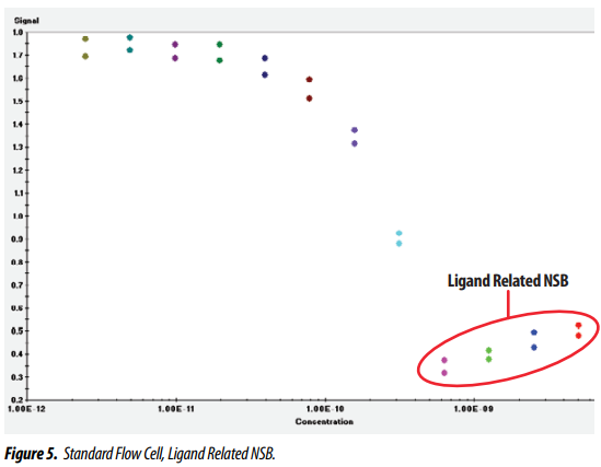
Ligand related NSB shows up with some sticky systems (see Tech Note 210 – Ligand Related NSB, TN210). When working at high ligand concentrations it appears as a positive slope in the saturated portion of the binding curve, as seen in Figure 5. The apparent increase in binding signal is caused by the ligand binding non specifically to the flow cell or beads. Siliconized flow cells have been tested with systems exhibiting ligand related NSB and they dramatically improved the problem.

These flow cells are an excellent option when baseline creep or ligand related NSB becomes a problem, but may not be completely effective with every system.

KinExA® is a registered trademark of Sapidyne Instruments Inc.